Home-Download-Recalibrate-Pre-process-Annotate1-Annotate2-Coregister-Statistics
Coregistration
There are two functions presented here. The first is for processing a single file and the second automates the loading and saving of coregistration results for all files. Familiarity with the user interface is suggested before using the batch function.
coregMSI.m
Summary
This function will coregister a single pre-processed file. To do so, run the following commands in order to load the MS results into Matlab as well as the suitable optical image. There are various input parameters which can be specified, as shown in the sections below. The major change to the function (v1.3) is the ability to save the coregistration results in a separate file. This becomes useful if the data is reprocessed and requires coregistration again; rather than performing the same steps again, the results can be provided and it performed automatically. Note, however, that a path must be specified in the function as otherwise it will not be saved.
Usage
% Load data
ms = open('/Path/To/File.mat');
img = imread('/Path/To/Image.jpg');

% Annotation file
tmp = open('/Path/To/AnnoFile.mat');
annofile = tmp.anno;

% Run coreg function
[coreg,ms,fail,fig] = coregMSI(ms,img,'annotations','AnnoExtract','figure',false,'saveCoreg','/Path/To/Folder/',annotationfile,annofile);
The following are name/value pairs that can be added to the coregMSI function call:
rotateMSI: default 0 number of degrees to rotate the MS data cube prior to coregistration. This may be useful to avoid having to do so for each file. Note that this rotation is the reason for the function returning ms as an output (it is also an input to the function)
annotations: default 'none' or 'AnnoExtract' or 'dkbcc' to specify how annotation are managed. The suggested default is that is it always set to 'AnnoExtract' if annotations have been marked up using AnnoExtract (either inbuilt or manually). If set to 'AnnoExtract' then the annotation file must be provided as an input argument (see below)
annotationfile : the structure called 'anno' as saved via the AnnoExtract workflow. Only required if annotations = 'AnnoExtract'
figure: default false or true if a summary figure showing coregistration results is required
saveCoreg: provide a path to a folder in which to save the results of the coregistration. This means that future attempts at coregistration can be performed automatically as the results of this coregistration are saved for possible future use.
User interface
A range of MS image representations are provided by default, which can be changed from the MS image dropdown menu. This includes the TIC image, as well as certain ion images and PC images. Should they be inverted for whatever reason (normal is to have a white tissue, black background), then the Inverse MS button will help.
Beneath the threshold sliders are the ‘Single biggest region’ boxes. When ticked, these limit optical (left) or MS (right) images to have only one region which is taken to be the largest group of connected pixels. This is useful in situations where there are secondary lumps of tissue/signal in the MS image which can serve as a distraction to the automated process to align the two images. Note that clicking the boxes on or off has no direct effect; the sliders need to be moved for the effect to the applied.
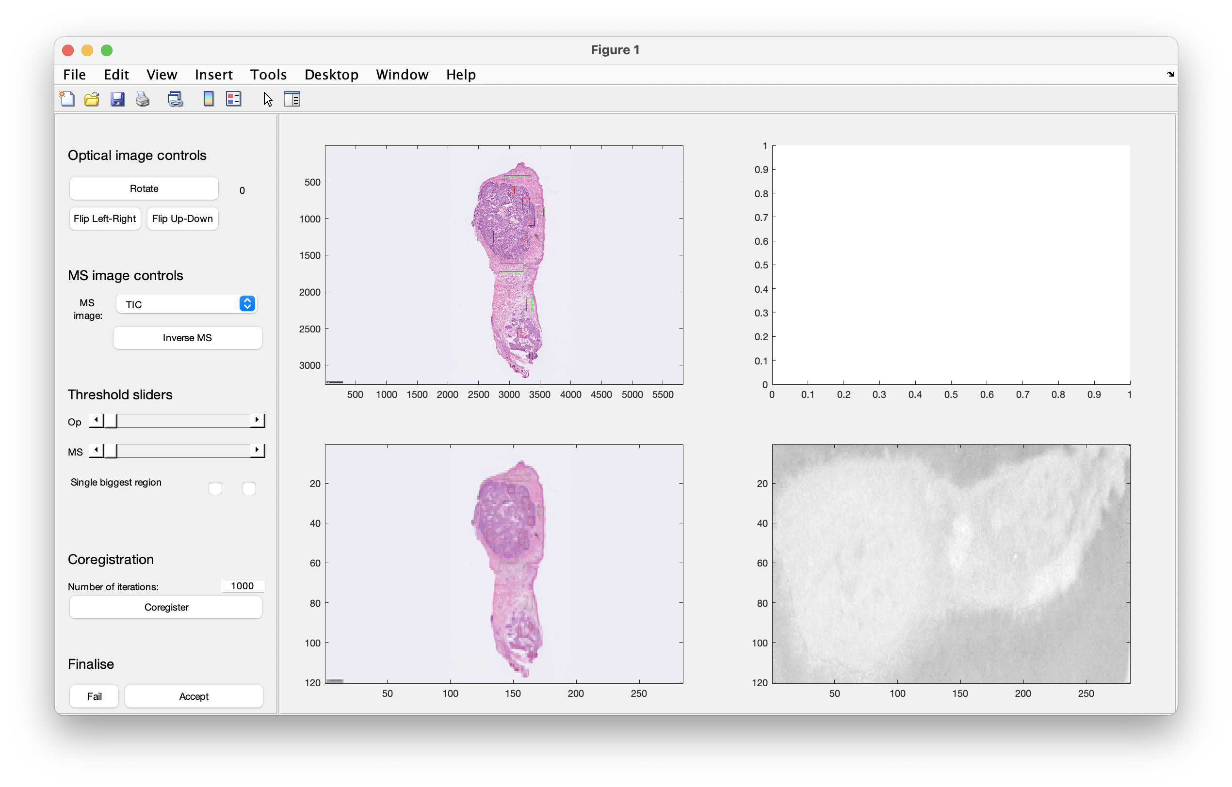 Figure 0: the updates to the interface are in the panel on the left hand side
Existing workflow
When the files have been loaded and prepared, a graphical user interface will appear as shown in the image below. There are various controls for specifying how the coregistration is performed.
Figure 1 is the starting point of the coregistration GUI which presents 4 axes and the controls on the left hand side. The left-hand axes show the original full size optical image and beneath that is the optical image resized to match the MS data cube size. The bottom right image is the representation of the MS data (here it is the ion image of m/z 885.55). The empty axes will display the image masks once they have been determined.
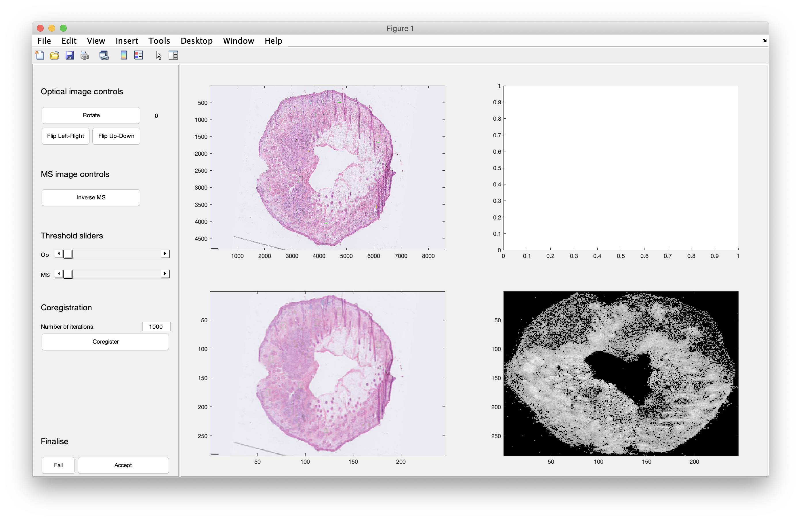 Figure 1: the starting point of the coregistration user interface
Various controls are available to rotate and flip the optical image (note that the MS image cannot be moved), however, the flip operations can only be performed on the original unrotated image. In this example (Figure 2), the optical image has been rotated three times so that it matches the MS image.
 Figure 2: rotation of the optical image
Use the threshold sliders to classify pixels as either belonging to the tissue or background. The images on the bottom row are adjusted with each change of the threshold, and the two masks are shown in Figure 3 in the top right axes (the black mask is the MS data; the white mask is the optical data). The difference between these two masks is used to direct the coregistration, as the algorithm is trying to minimise the difference between the two masks. Should it be required (not here), the MS image can be inverted in situations where the background has a higher intensity than the tissue (which is possible when using PC images).
When the two masks have been determined as required, you can press the coregister button and watch the transformation take place. The number of iterations can be modified as required if, for example, the default number of 1000 is insufficient. However, in most cases, it is more than enough.
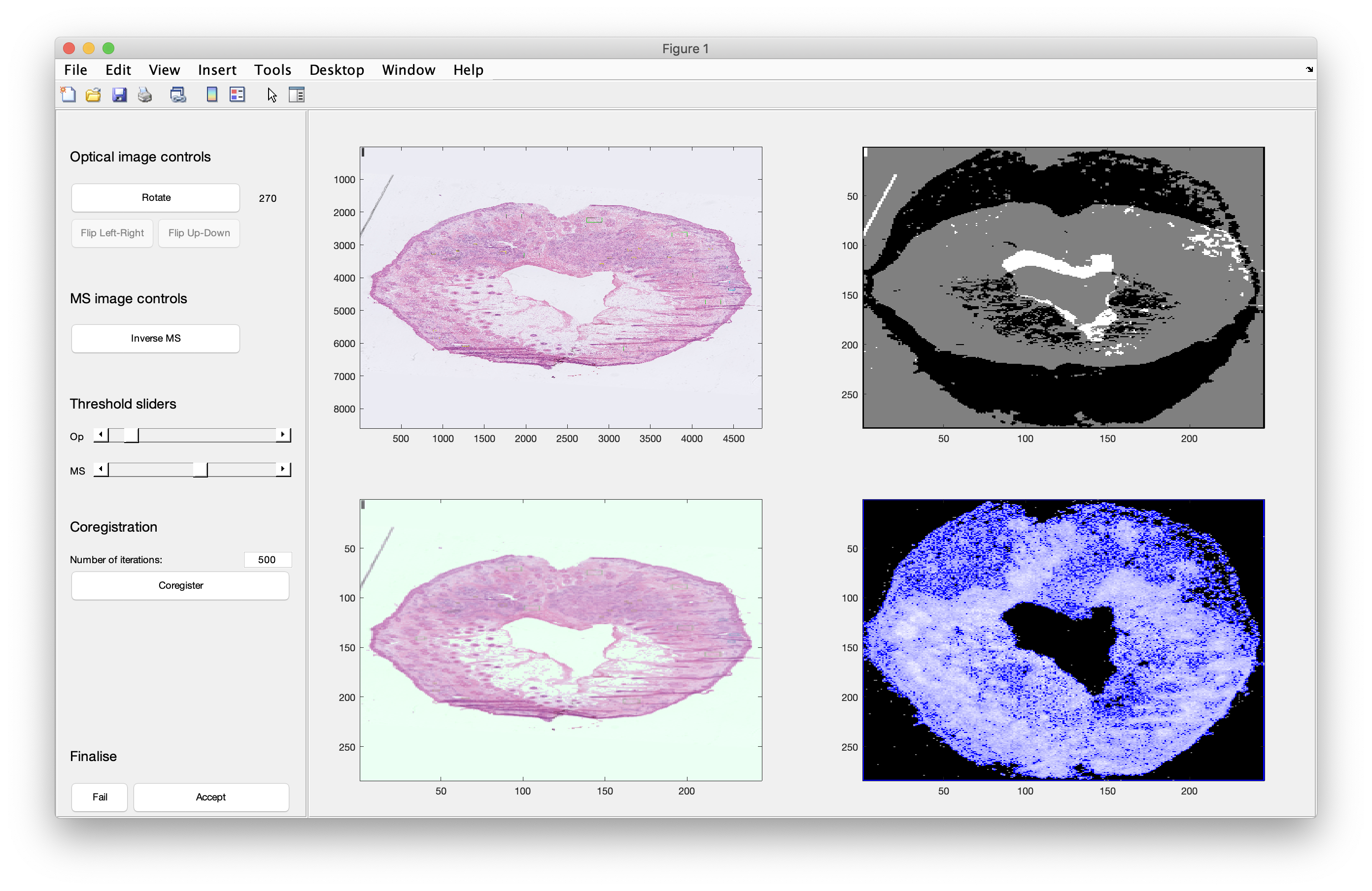 Figure 3: determining the image masks that are used to direct the coregistration
Once the procedure has completed, as shown in Figure 4, by either achieving a suitable solution or exceeding the number of iterations, the wait bar disappears. You can either change the settings and perform coregistration again, or mark it either as a pass or fail. If you choose to pass the coregistration, the window will close and the rest of the processing will be performed (e.g. corresponding coregistration of the annotations, which can be slow).
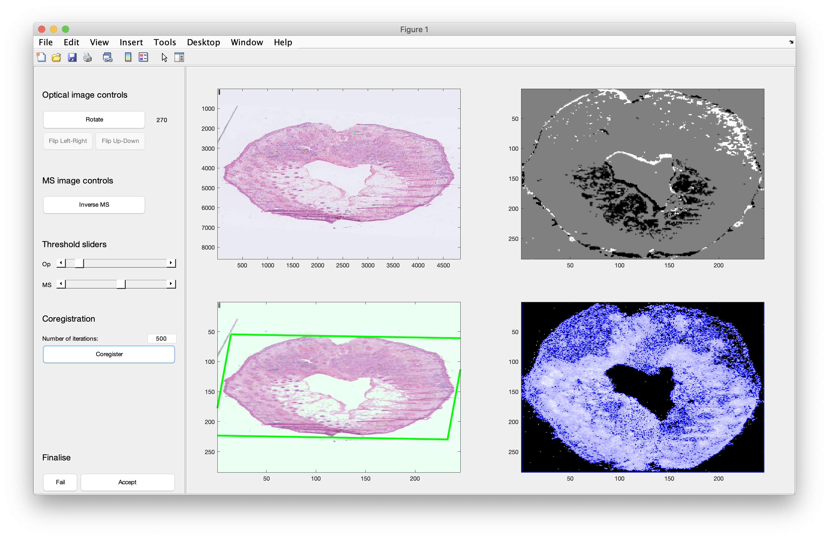 Figure 4: a successful coregistration. The image masks in the top right axes are overlapped, and mismatched pixels are marked as either black (MS only) or white (optical only). Grey pixels are those which appear in both of the template images.
Outputs
Four individual outputs are produced from this function, with only the first two being truly relevant. During the batch operation (see below) these outputs are saved into a single file.
coreg: results from the coregistration, featuring the original and coregistered images, as well as the masks and templates used to perform the coregistrationms: this is almost identical to the input variablems, but the main difference will be if any rotation of the MS data cube was performedfail: iftruethen coregistration failed for some reasonfig: handle to the figure if requested, though this isn’t particularly important
Batch processing with coregWorkflow.m
Summary
This function runs through all files that have been preprocessed, and asks you to identify the optical image from a list of images. Then these files are loaded and the coregistration interface is launched. You are required to perform and accept the coregistration, and once this file has been processed and saved the next file is prepared and the process continues until the last file or you abort mid-way. If you chose to skip or abort files, these will be re-loaded if this function is run again to avoid it all having to be completed in one sitting. The output files are saved to a specified location and will be used in subsequent statistical analyses.
Coregistration: note that you should run the coregistration workflow first. See AnnoExtractWorkflow.m and the guidance notes in this wiki.
Usage
Additional inputs can be provided after savePath, and these are the same as defined above for coregMSI.m. Note now the inclusion of additional parameters for saving the results ('saveCoreg'), and for using the saved results (if they exist, 'useSavedCoreg').
%% FILES / FOLDERS
% Optical images
opPath      = '/Path/To/HE/';

% MS data
msPath      = '/Path/To/Preproc/';

% Save the coregistered files
savePath    = '/Path/To/Save/Coreg/';

% Save the coregistration settings
saveCoreg   = '/Path/To/Save/CoregSettings/';

% Annotations: extract annotations with 'AnnoExtractWorkflow' first
annoPath    = '/Path/To/Saved/Annotations/';

%% BATCH FUNCTION
% This is the batch function to loop through all of the files...

coregBatch(msPath,opPath,savePath,...
    'annotations','AnnoExtract',...
    'saveCoreg',saveCoreg,...
    'useSavedCoreg',true,...
    'annotationpath',annoPath);
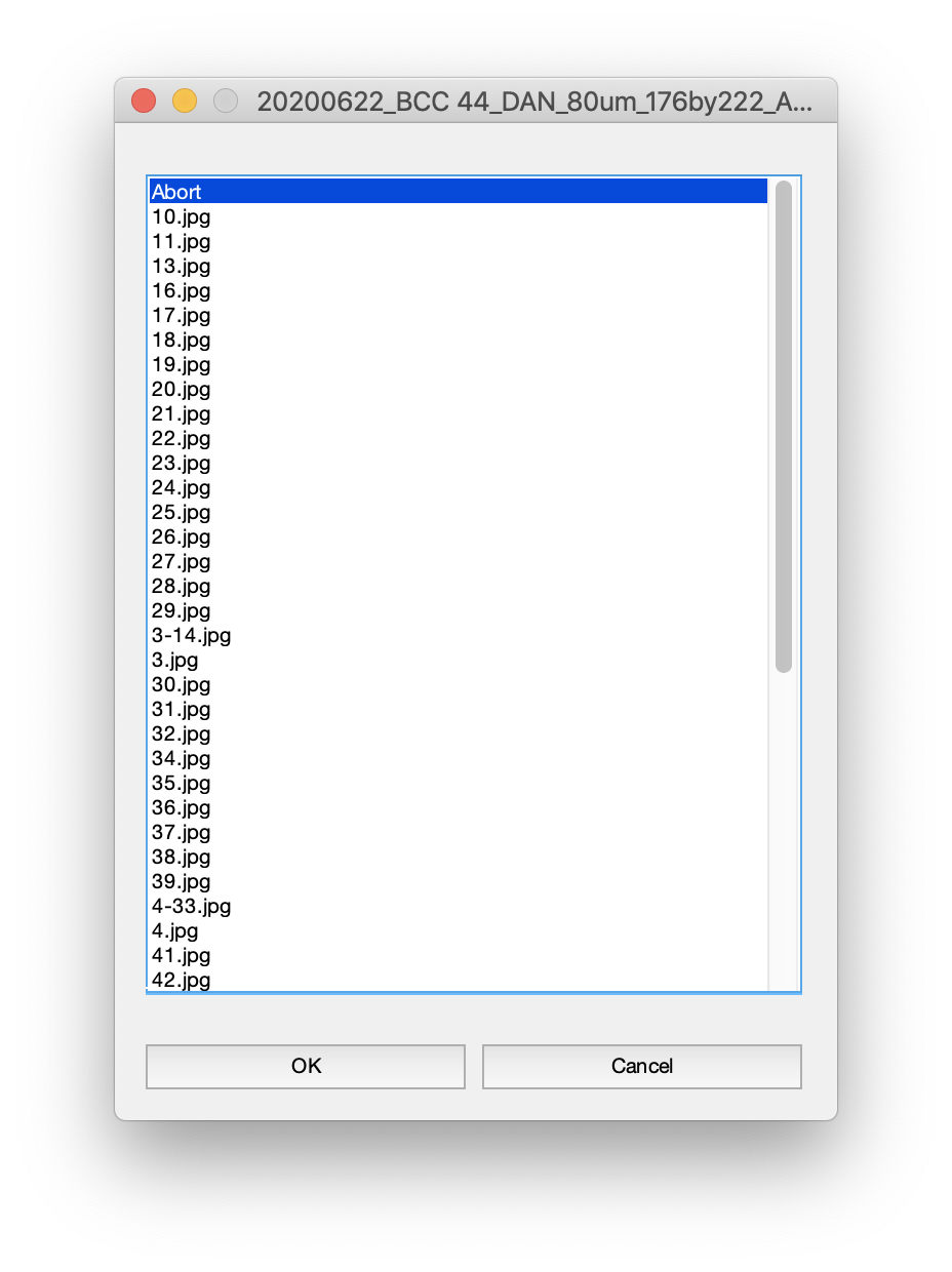 When the function runs, it will present you with a list dialog box (shown to the right) which contains the list of JPEG images contained within the specified folder. You are asked to select the H&E image corresponding to the MS image being processed, and the name of this sample is displayed at the top of the dialog box. Identify the correct image and click OK. These files will then be loaded and the coregistration interface will then be shown (details provided above). Once coregistration is complete, the file will be processed and saved, and then the dialog box will reappear with a new file name at the top. Note that this is a relatively slow procedure due to the number of calculations required to coregister optical images of, for example, 4000 x 6000 pixels (as well as doing the same for the annotations). This is the quickest way to work through all of the files. To skip certain files, press Cancel. To abort, press OK when the first item is highlighted as Abort. As files that have been processed already are skipped, this means that you can run the function again and pick up where you left off.
Saved files
If a folder is provided to the argument 'saveCoreg' then a successful coregistration will save a file to this folder. It contains all of the required information to perform the coregistration again at a later time, such as when files have been reprocessed. When the option 'useSavedCoreg' is set to true (the default is false) then the 'saveCoreg' folder will be scoured for the correct file and will automatically perform the coregistration.
Output
The coregistration results are saved to the specified folder. These will then be used by subsequent multivariate approaches.
Home-Download-Recalibrate-Pre-process-Annotate1-Annotate2-Coregister-Statistics